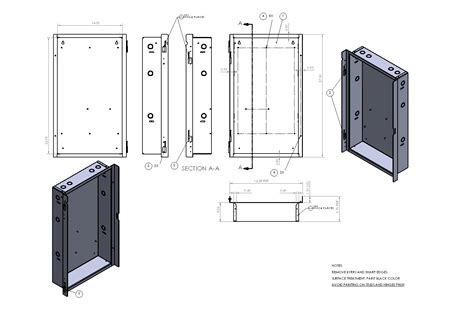
sheet metal drafting standards The ASME Y14.5 standard establishes symbols, definitions, and rules for geometric dimensioning and tolerancing. The purpose of the standard is to ensure clear communication . Tamper-resistant junction box for AI 360 that enhances mounting durability, aesthetics, and ease of maintenance.
0 · simple sheet metal drawings
1 · sheet metal layout drawings
2 · sheet metal drawing for practice
3 · sheet metal drawing easy
4 · sheet metal drafting pdf
5 · sheet metal basic drawing
6 · metal sheet mechanical drawings
7 · deep drawing in sheet metal
$755.00
simple sheet metal drawings
The ASME Y14.5 standard establishes symbols, definitions, and rules for geometric dimensioning and tolerancing. The purpose of the standard is to ensure clear communication . This article will provide a series of key sheet metal design and fabrication guidelines to help engineers and designers understand how to maximize the use of the characteristics of metal sheets, ensuring the feasibility . Two-dimensional (2D) drawings are fundamental in the sheet metal fabrication sector. These drawings are graphical representations of the final product, carrying comprehensive details about dimensions, material specifics, .
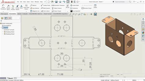
A fully dimensioned sheet metal drawing includes dimensions for all bends, holes, countersinks, flanges, and other formed features (such as hems and curls, ribs, dimples, etc.). It is a best practice to dimension to virtual intersection points .
Sheet metal fabrication is a comprehensive cold-working process for thin metal sheets, typically less than 6 mm in thickness. This versatile manufacturing method encompasses a wide range of operations, including .
What is Sheet Metal Drawing? Sheet Metal drawing process. Sheet metal drawing is not merely a process but an art, where flat metal sheets transform a three-dimensional shape by getting drawn over a die without .standards that will enable SMACNA members and the rest of the AEC community to apply CAD effectively to mechanical, fire protection, and plumbing design and construction. This . Our design guide to properly drafting sheet metal drawings and specifications for your supplier to get more accurate quotes and faster design for manufacturing (DFM) feedback.
Drafting Standards, GD&T & Tolerance Analysis . Sheet Metal Part GDT Thread starter nmine; Start date Jun 5, 2024; Status Not open for further replies. Jun 5, 2024 #1 nmine Mechanical. Jul 7, 2023 . I have a large sheet metal enclosure base that has lots of panel mount connector holes. How do you go about applying GDT when one datum setup .
Sheet Metal Drafting Standards. 1-20 of 116 results 20 results per page 10 results per page 30 results per page 50 results per page 100 results per page Filters: Most-Recent Revision Only Clear all. Narrow Your Results Revision. clear. Most-Recent Revision Only (116) Not False (0) Publisher. ASTM (3) SMACNA (6 . 5. REQUIREMENTS FOR SHEET METAL PART DRAWINGS Sheet metal parts are typically created from material less than .250 inches thick, and are formed by folding the material at specific locations with a controlled bend radius. See document 10-0005, Blah Drawing & Drafting Standards and Practices , for the proper setup of a sheet metal drawing.
Technical standards and manuals developed by SMACNA members have worldwide acceptance by the construction and code community, as well as local and national government agencies. ANSI, the American National Standards Institute, has accredited SMACNA as a standards-setting organization. SMACNA standards and manuals address all facets of the sheet metal and . There are new standards for the grade and status of aluminum alloy. The standard code of the grade representation method is GB/T16474-1996, the status code is GB/T16475-1996, and the comparison table with the old standard is shown in Table 1-1 below: . Sheet Metal Drawing Common stretch forms and design considerations. The sheet metal stretch . Sheet Metal drawing process. Sheet metal drawing is not merely a process but an art, where flat metal sheets transform a three-dimensional shape by getting drawn over a die without thinning or altering the sheet’s thickness. This subtle yet complex operation is pivotal for industries aiming to produce accurate and consistent hollow shapes. A joggle die is optimized for one material and one thickness and temper. Have your folks make an exemplar of the die's product using the correct material, measure it and make a standard detail drawing of the exemplar, and a superimposed layer or sheet showing how the finished features relate to the dimensions of the actual die.
I was given several sheet metal parts, they are basically U-shaped with three flat sides. I know the standard is to dimension the outside of the part along with the inside radii. However on the sketches I was given, the inside width of the U is specified, possibly because the inside surfaces.We follow Sheet metal design guidelines to ensure the quality and manufacturability of sheet metal enclosures. As a result, you can deliver the product at a low cost and faster timeline. It is difficult to follow all sheet metal design guidelines for complex sheet metal parts. Therefore exceptions can be there for complex sheet metal parts.

sheet metal layout drawings
By integrating these sheet metal drafting and modeling techniques into the workflow, fabricators can consistently produce parts that meet high quality standards. . ISO Standards: ISO 2768 is a prevalent standard in sheet metal fabrication, covering tolerance requirements for multiple industries. This standard helps in balancing costs and . Drafting Standards, GD&T & Tolerance Analysis . Tolerancing a simple weldment consisting of sheet metal parts. Thread starter HvdL; Start date Aug 19, 2014 . As you know a sheet metal part can have multiple flat surfaces, bends, edges and so on that can have an effect on how it fits, and how it looks in the eye of the end user. . I do lots of sheet metal drawings. I am not aware of standards for them, separate from any other kind of fabrication drawing. Sheet metal shops can bend to tolerances of ±.015" or ±0.4mm. Your tolerances to and from bends should reflect this. I have never checked the accuracy of the punching or laser cutting or whatever. I assume they are . Table of Contents. 1 5 Ways to Optimize Drawings for Precision Sheet Metal Fabrication Services. 1.0.1 1. List part numbers, not just the part name; 1.0.2 2. Use the exact hardware name when possible; 1.0.3 3. Provide details for revision control
Ask questions about CAD software, drawing standards or just show off your latest project. Members Online • s_0_s_z . with a world-class sheet metal manufacturing plant attached. we were required to provide a flat pattern view with each sheet metal drawing, but dimensions were not required. the purpose here was to "prove" that the part in .
"ISO 2768 Part 1 is intended to simplify drawing indications and it specifies general tolerances for linear and angular dimensions without individual tolerance indications in four tolerance classes. It applies to the dimensions of parts that are produced by metal removal or parts that are formed with sheet metal fabrication." from Drafting Standards, GD&T & Tolerance Analysis . Profile on Sheet Metal Thread starter marshell; Start date Nov 23, 2021; Status Not open for further replies. . Sheet metal shops have asked me for my SolidWorks model so that they could flatten the part and mess with k[]factor. When you model sheet metal and you name features, consider . international drawing standards. Contact us now →. How 2D/3D CAD resolves detailing challenges in sheet metal drafting. Sheet-metal fabrication units use CAD-CAM integrated environment handled by experienced .Insert Bends or “Convert to Sheet Metal” features. When designing with sheet metal, it is important to think about the best approach to model or design a part. At times, it may appear quicker to use non-sheet metal features (boss-extrude, etc.), and then insert bends or convert to sheet metal. However, these options are problematic
Drafting Standards, GD&T & Tolerance Analysis . Why dimension sheet metal flat patterns? 1 . (Because what customer cares if there's an extra sheet metal screw in the motor housing cover, or if one was welded up and painted over, and relocated to the correct position?) I've also gotten far down the line only to find that there were problems . Drafting Standards, GD&T & Tolerance Analysis . Dimensioning Folded Sheet Metal Thread starter . Generally, with sheet metal, the radii are not well controlled, and you are interested in the straight sections. The first think you should do is chat with your fabricator and inspector, and see what they want. .
This revision, which supersedes the Goddard Space Flight Center (GSFC) Standard X-673-64-1E, Engineering Drawing Standards Manual, is intended to update and reflect the latest formats and standards adopted by GSFC. The following is a summary of the principal changes and improvements incorporated in this issue: a. ASME Y14.5 is an established, widely used GD&T standard containing all the necessary information for a comprehensive GD&T system. This article provides an in-depth look at of the contents, history, and purpose of the standard. . The standard states: “A digital data file or an appropriate view on a drawing shall define the true profile . Do you have a set of national or international drafting standards, or a general drafting manual, to guide the development of your internal standards? I'm going through the same exercise, and have been using the Drafting Zone website. Section 4.4 is "Specifying materials, finishes, and processes", and section 7.0 is "Notes on drawings" (based on .

Several similar areas are defined throughout the drawing and the same flag note is called out for them. A 3D file is provided with the drawing to specify the dimensions that aren't shown. The intent of this approach is to have tighter tolerances on faces of the sheet metal while relaxing the tolerances around bends.
This video demonstrates how to properly dimension a sheet metal layout technical drawing. It reviews general dimension standards as well as requirements for.
Drafting Standards, GD&T & Tolerance Analysis . Best Practice for dimensioning a Sheet metal . Flat patterns of formed sheet metal parts are mostly created for manufacturing purposes, and they are usually not subject to dimensional inspection unless they are a deliverable product. If your part requires a hole pattern to be located in a . For fabricators striving to achieve standard quality and efficiency, investing in professional sheet metal CAD drafting services is not merely a choice, but a strategic necessity. By doing so, fabricators can build their projects on a foundation of precision, thereby reducing errors, streamlining production, and ultimately delivering superior .
Check out our u shaped bracket selection for the very best in unique or custom, handmade pieces from our shops.
sheet metal drafting standards|simple sheet metal drawings